This tutorial shows you how to generate custom clocks inside your FPGA using the simple Clocking Wizard. Easily create clocks at any speeds such as 100Mhz, 75Mhz, or 50Mhz from the 32Mhz oscillator connected to your Papilio FPGA. The Xilinx clocking wizard easily generates custom clock speeds with all of the Global Clock buffers and supporting circuitry automatically created for you. It is definitely the easiest way to generate custom clocks for your FPGA project.
Create a Xilinx ISE Project
Please follow the Getting Started with Xilinx ISE WebPack guide for the Papilio FPGA boards to get a new project setup in Xilinx ISE. You can also download the existing Xilinx ISE project from GitHub. Be sure to download the correct ucf file for your Papilio board from the GadgetFactory ucf Downloads section. The project we will be using has counters setup on the pins of the Papilio FPGA board. In this tutorial we will use the Clocking Wizard to attach a different clock to the counters.
Add VHDL Source Code
Add the following source code to your project:
library IEEE;
use IEEE.STD_LOGIC_1164.ALL;
use IEEE.STD_LOGIC_ARITH.ALL;
use IEEE.STD_LOGIC_UNSIGNED.ALL;

entity WebPack_QuickStart is
    Port ( A : out  STD_LOGIC_VECTOR (15 downto 0);
           B : out  STD_LOGIC_VECTOR (15 downto 0);
           C : out  STD_LOGIC_VECTOR (15 downto 0);
			  clk : in STD_LOGIC);
end WebPack_QuickStart;

architecture Behavioral of WebPack_QuickStart is
 signal counter : STD_LOGIC_VECTOR(47 downto 0) := (others => '0');
begin
	--Counter to drive blinking pins
	count: process(clk)
   begin
     if rising_edge(clk) then
       counter <= counter+1;
     end if;
   end process;
	--Pins are connected to the counter to cause blinking at varying frequencies
	A <= counter(35 downto 20);
	B <= counter(31 downto 16);
	C <= counter(15 downto 0);
end Behavioral;
This code pulls the 32Mhz clock from your Papilio FPGA board and then uses it to drive a 48 bit counter. The outputs of the counter are attached to the output pins of your Papilio FPGA board.
Verify your ucf file
Open the ucf file, unique to your Papilio board, that you should have downloaded and added to the project earlier. You should see the following important sections:
The clock definition
There should be a line that defines CLK and sets the Period to 31.25 which is the period for a 32Mhz clock. It will look something like this but the LOC could be different depending on your Papilio board.
NET CLK LOC="P94" | IOSTANDARD=LVTTL | PERIOD=31.25ns; # CLK
Define Row A,B,C pins
You should also have A(0..15), B(0..15), and C(0..15) defined which sets up the locations of the pins on the Papilio FPGA.
Comment all unused lines from the ucf file
To avoid any errors you should comment out any lines from the ucf file that are not being used.
Run the clocking wizard to generate your desired clocks
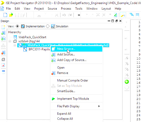
Right click your top level project file and choose “New Source”
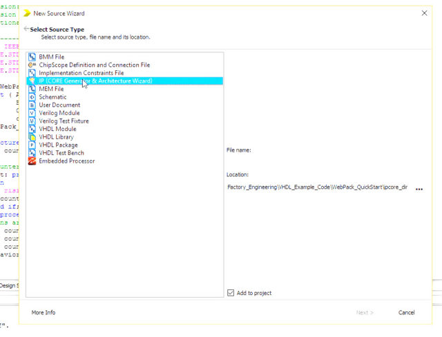
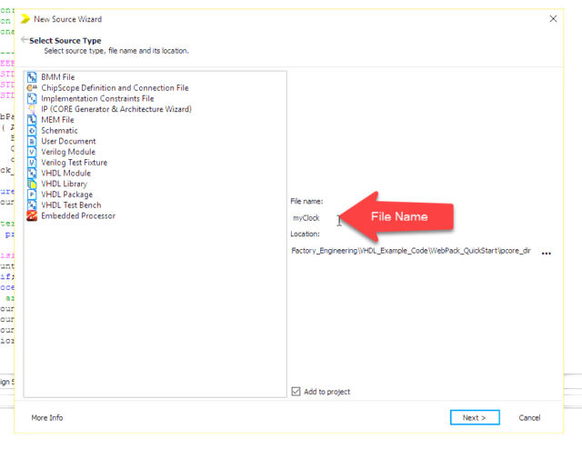
Click on “IP (Core Generator & Architecture Wizard)” and provide a file name and hit “Next”:
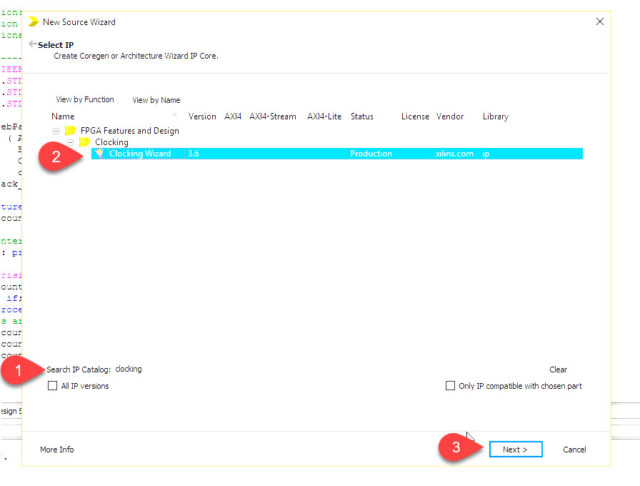
- Type “clocking” in Search IP Catalog
- Select “Clocking Wizard”
- Click Next
- Click Finish on next page
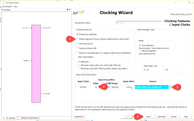
In Clocking Wizard Page:
- Uncheck “Phase alignment”
- Type 32 into the Input Clock Primary Value Field (This says our oscillator provides a 32Mhz clock)
- Make sure source is a “Single ended clock capable pin”. (Our Oscillator is connected to a special clock input capable pin. We could be connecting the input into a differential clock input or an internal clock input…)
- Click Next
In Output Clock Setting Page:
This is where we define the frequency of the clocks that we want to generate. We can put just about anything in here and it will tell us how close it can get.
We are going to create three clocks outputs: 25Mhz, 10Mhz, 5Mhz.
Be sure that Drives is set to BUFG since we want our generated clocks to be fed into a Global Clock Buffer which makes them easier to use within the FPGA.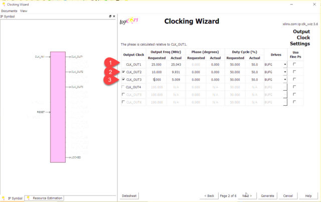
In I/O and Feedback page uncheck the RESET and LOCKED signals since we will not be using them in our simple clocks.
Click Generate to complete the wizard – you will see a new *.xco file show up in your project:

Instantiate clocks into your project
Now that we have run the clocking wizard and we have an *.xco file in our project we need to actually place those clocks into our VHDL code and make use of them. The easiest way to do this is to use the HDL Instantiation Template included with the *.xco file.
Video Overview
In the Projects Design Pane:
- Click on your *.xco file that you created in the previous step.
- Go under Processes and expand the Core Generator
- Double click “View HDL Instantiation Template”
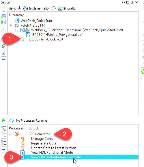
This will open up a *.vho file in the text editor. If you scroll down you will see two sections. The first section defines the component and the second section defines how to instantiate that component.
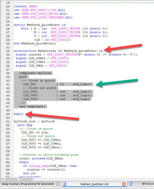
Copy the component section
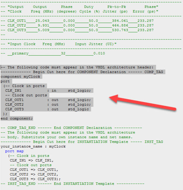
And paste it into your top level VHDL file. It must be placed in the architecture header portion of your VHDL file – so anywhere between architecture and begin:
Copy the Instantiation section from your *.vho file:
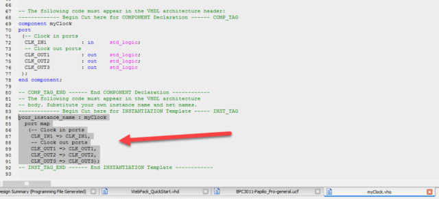
And paste it into the architecture body section of your top level VHDL file. So anywhere between begin and end:
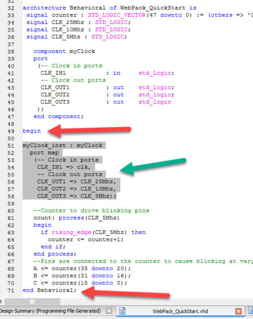
Optional – rename the clock signals so they show what frequency they provide.
The *.vho template file uses non-descriptive names for the clock signals. It just calls them CLK_OUT1, CLK_OUT2, and CLK_OUT3. This is going to make it very hard to keep track of what frequency each clock provides so it is a good idea to rename those signals to something more descriptive such as CLK_25Mhz, CLK_10Mhz, and CLK_5Mhz. You will do that on the right side of the line where Clock out ports is defined:
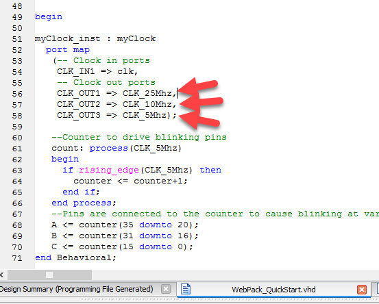
Next we need to declare the clock signals, whether you renamed them or not we will need to declare the signals in the architecture header section (the names must match what was used in the instantiation):
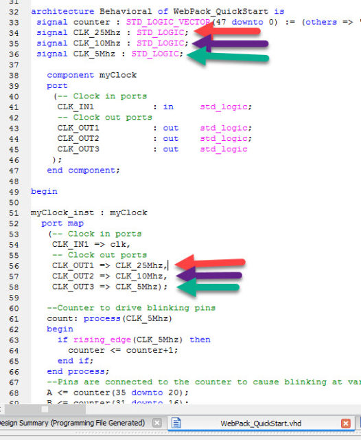
Finally we can use the clock signals! In this example we will change the count process to use a different frequency then the 32Mhz clk signal. We can use our newly created clocks: CLK_25Mhz, CLK_10Mhz, or CLK_5Mhz. Just change the count process to use the desired clock – there are two places to make the change:
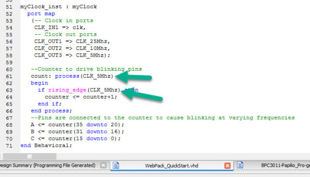
You can now synthesize the design with the new clock frequencies driving the counters. If you connect LEDs or a multimeter to the pins you should see the rate that they blink changes depending on the clock that you use.
(Optional) Make design easier to share by removing *.xco file.
Sometimes it is desirable to ship your Xilinx ISE project without including the *.xco wizard file. One example is if you are going to check your project into a revision control system like git. The *.xco file has a bunch of additional files that you have to include from the ipcore_dir folder and it can be tedious and error prone to include them into git. There is a trick that you can do to get rid of the *.xco file and include the generated clocks as a standard VHDL file in your project. You lose the ability to change the configuration using the clocking wizard, but this is normally a good thing…
