Overview
GadgetBox tackles the biggest problems with current IoT devices – shield stacking, easily adding hardware, hardware compatibility, and an enclosure for your project. There are lots of IoT hardware options out there but none of them have thought the problem all the way through, so what we end up with is either a crazy tower of shields or peripherals soldered on with jumper wires. Not something we can proudly show our friends and family, let alone put into use in our homes.
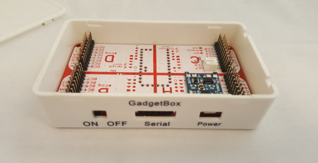
GadgetBox starts with a case and builds from there – so the end result is an attractive, functional device with all of the electronics safely contained in the case.
Inside the GadgetBox case is a motherboard that provides all of the circuitry to charge and use a Lipo battery pack, provide higher current to your peripherals, and organizes all IO pins into the Universal eCog scheme. A motherboard for all of the most popular IoT devices is currently in the works – Arduino, Teensy, Pi Zero, ESP8266, etc.
eCogs are Universal peripherals that just snap into the motherboard and form the top of your enclosure. Only the hardware that is needed by the end user is exposed to the outside world, everything else is tucked inside the enclosure. Because the motherboards are designed using the Universal eCog scheme you can freely interchange your eCogs between motherboards. If you have an SD card eCog shouldn’t you be able to use that same eCog with the Arduino, Teensy, Pi Zero, and ESP8266? Of course you should, the Universal eCog scheme makes that possible.
Specifications
- Enclosure for Arduino Mini Pro Clones
- Universal eCog Scheme for Universal Hardware Modules
- Battery Powered
- TP4056 Charging Circuit and USB Power
- Power Switch
- 3.3V Logic
Pre-Orders
Pre-Orders are available at the Gadget Factory store.
Hardware
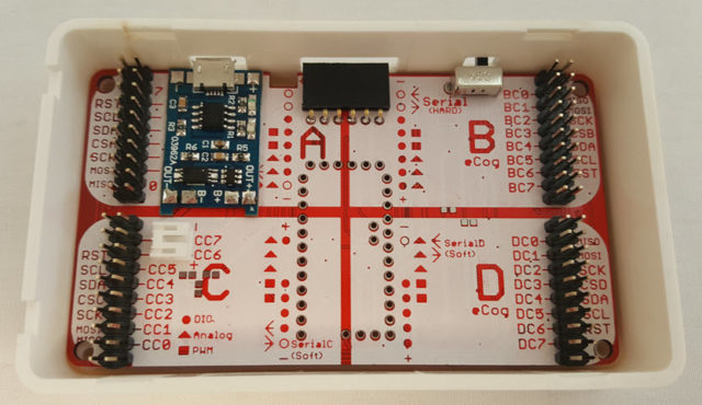
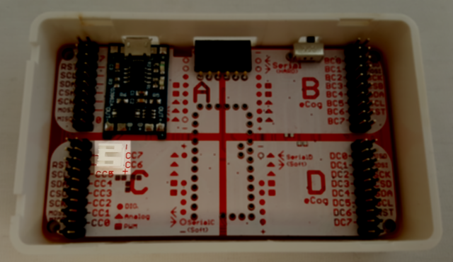
GadgetBox Overhead View
FTDI Programming Header – Connect an FTDI USB to Serial module to this header to program with the Arduino IDE.
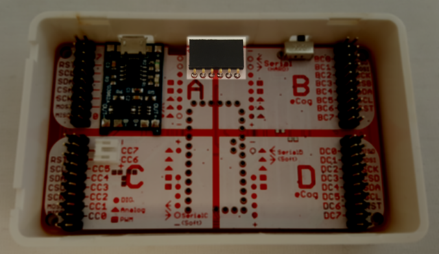
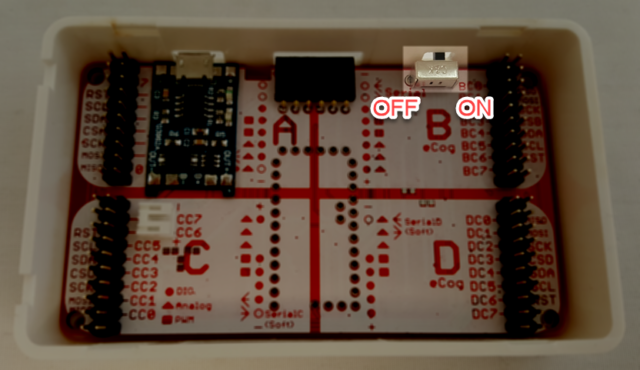
On/Off Power Switch – This power switch is between the Output of the TP4056 Power/Charging Module and the VIN pin of the Arduino Mini Pro Clone Module. Putting this switch in the Off position will disconnect power from the battery and power connected to the USB connector of the TP4056 module. It will not disconnect power from the VCC pin on the FTDI programmer header.
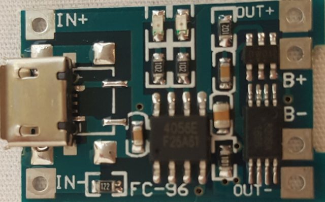
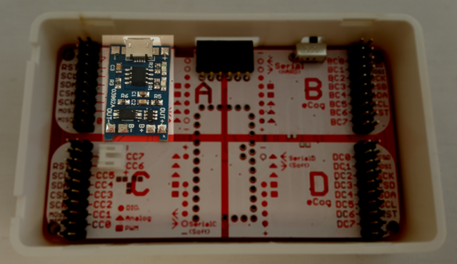
TP4056 Power/Charging Module – This module can either provide power to the Arduino Mini Pro Clone through the Micro USB connector or it can Charge a battery connected to the battery connector. It can also power the Arduino Mini Pro Clone while charging the battery.
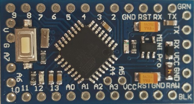
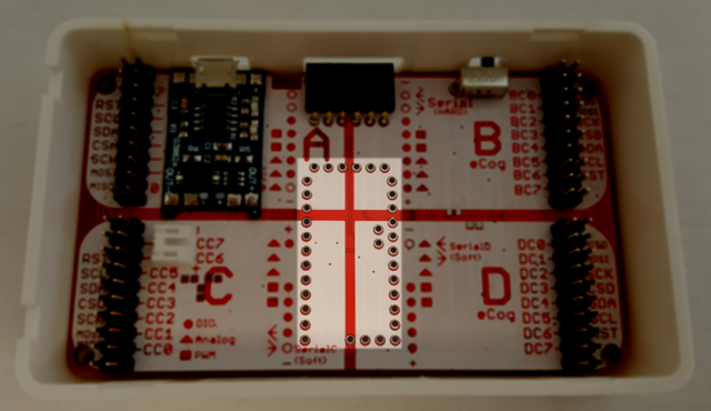
Arduino Mini Pro Clone – Solder in your Arduino Mini Pro Clone module here.
You will want to be sure to get the Arduino Mino Pro Clone that matched the footprint highlighted below. You will also want the 8Mhz, 3.3V module as all eCogs are designed to use 3.3V logic and a 5V module could damage the eCogs.
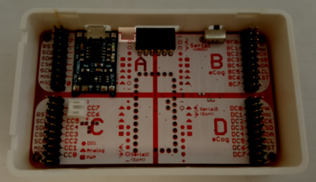
Cutout for the Battery Cable – This slot is intended to let you connect a battery on the top but route the cable through the slot so the battery can be underneath the motherboard.
Battery Connector – Use this battery connector to connect any single cell Lithium Ion batteries to the GadgetBox. The batteries available from Adafruit have been tested for the correct polarity.
How to Connect eCog Hardware
Attaching eCogs is very simple, you just need to:
- Match the shapes printed on the eCog to the shapes on the motherboard.
- Make sure none of the shapes overlap.
- Understand any potential conflicts presented by shared pins on this motherboardboard.
Match Shapes
Take a look at your eCog and you will see shapes printed on the board. You will then hold your eCog next to the eCog slot you want to connect to on your motherboard and make sure the same shapes are in the same locations. This will ensure that you are matching the correct pin functions to their locations on your motherboard. If the eCog has no shapes then that means it uses the SPI or I2C bus and therefore you can plug it into any eCog slot. The possible shapes are:
- Circle – This is a Digital IO pin
- Triangle – This is an Analog pin, Analog pins can usually be both Analog or Digital IO pins, if this is the case then there will be a Circle and a Triangle marked on the Motherboard.
- Square – This is a PWM pin, PWM pins are always PWM and Digital IO pins too. You should see a Circle and Square on the Motherboard.
- Arrow – This indicates a UART, an Arrow pointing at the Circle indicates a Receive (RX) pin for the microcontroller. An Arrow pointing away from the Circle indicates a Transmit (TX) pin for the microcontroller. There will be an indication of whether this is a Hardware or Software UART.
Avoid Overlap
Look at the shapes that are on your eCogs, when you put two eCogs in the A and B or C and D slots make sure that none of the shapes overlap. For example if you have two eCogs and each of them have four Circles you should see that putting them in adjacent eCog slots will result in there being no overlapping of the shapes. But if you have an eCog with 6 Circles and another eCog with 4 circles and you put them in adjacent eCog slots you will see that the middle two Circles overlap and you will have a pin conflict. Your best option in this scenario is to move the eCog with 6 Circles to be adjacent with a SPI or I2C bus eCog which will not use the GPIO pins. (Depending on the Motherboard some SPI eCogs will use the first GPIO pin, see the next section.)
Understand the Potential Conflicts on the GadgetBox Arduino Pro Mini Clone Motherboard
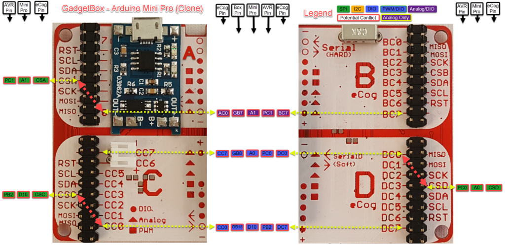
Sometimes there are just not enough pins to realize the Ideal Universal eCog Scheme layout and tradeoffs have to be made. These tradeoffs are denoted by shapes that are just outlines and usually indicate that a pin is shared with something that can cause a conflict when used. Here is a list of the potential conflicts with the Arduino Mini Pro Clone:
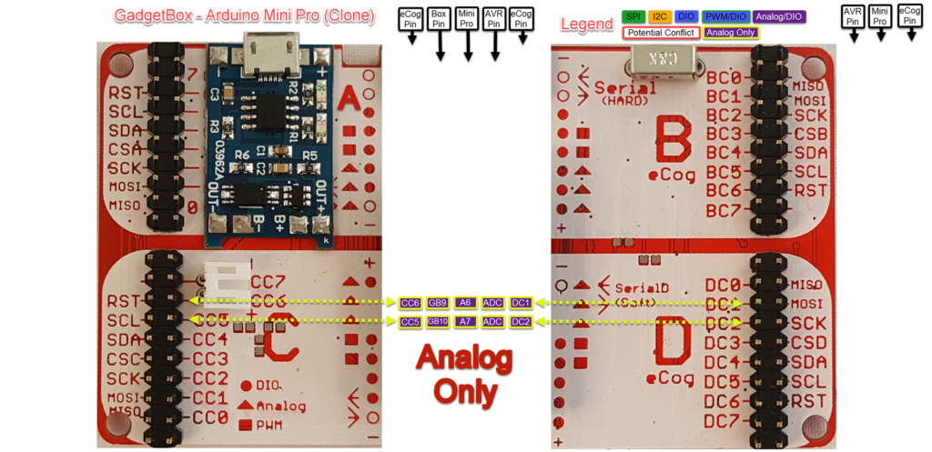
- The first thing to point out is that GB9 and GB10 are Analog only pins, they do not have Digital IO capability. You can see this on the Motherboard because there is no Circle in those locations, just a Triangle for Analog functionality. Avoid plugging in any eCogs that require Digital IO in those locations. It affects DC1, DC2, CC5, and CC6.
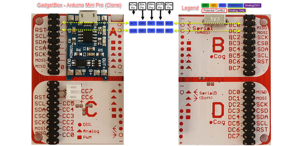
- The first two pins GB0 and GB1 are the Hardware Serial pins which is denoted by the Circles just being outlines. When you program the board using the FTDI programming header any DIO pins connected here can conflict with the programmer being able to program the board. It might be necessary to remove an eCog that has DIO pins in these locations from the Motherboard to successfully program the board. Your best bet is to avoid putting any eCogs that use DIO in eCog slot B.
- On eCog slots A, C, and D the SPI Chip Select pin is shared with the first DIO pin on the eCog slot. If you place an SPI eCog into these slots then the first DIO pin will be used. You will only have a conflict if you plug an eCog into the adjacent slot that uses the 8th GPIO pin. At this point there are no such eCogs that do that so there should not be any conflicts…
- Finally, the adjacent eCogs A and B and C and D share pins; AC7 is the same pin as BC0 and is otherwise known as GB0. The Universal eCog Scheme was designed to accommodate this and it is only an issue when an eCog uses more then 4 DIO pins, just be sure to follow the no overlap rule.
Pinouts
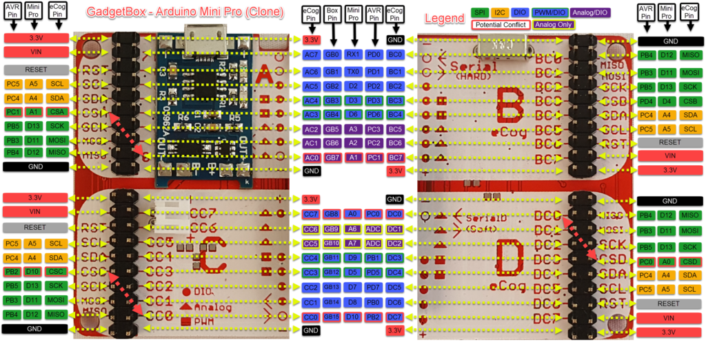
Pin Diagram
Potential Conflict Pins
This diagrams the locations where there are potential pin conflicts.
Analog Only Pins
Hardware UART
These pins are shared with the FTDI Programming Header, take care when using these pins with an eCog as it can interfere with programming the Arduino Mini Pro module.
Assembly
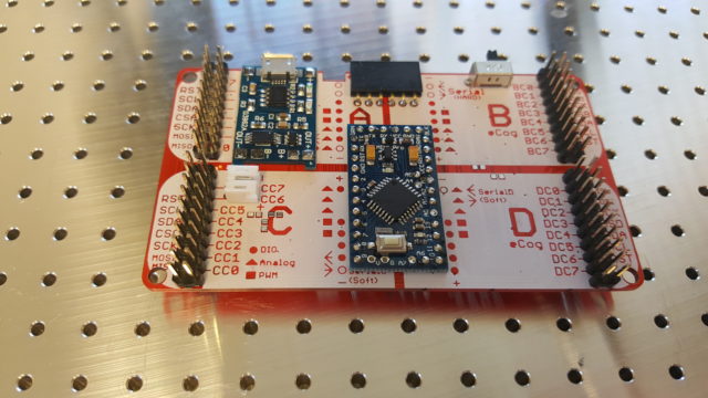
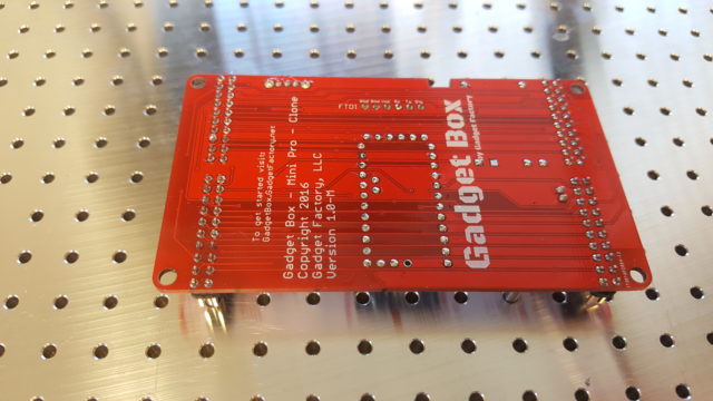
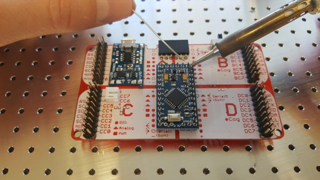
Before assembly consider the different soldering options. We recommend that you directly solder the battery/power module and the Arduino Mini Pro (clone) module to the surface of the motherboard like this: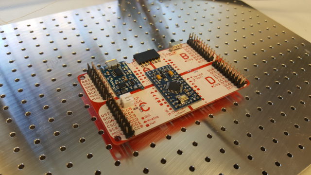
The other option is to use standard male headers like this:
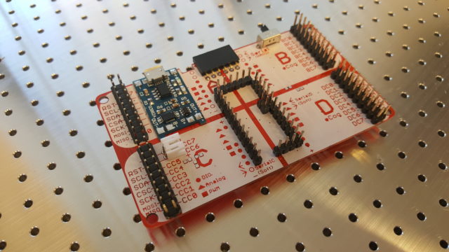
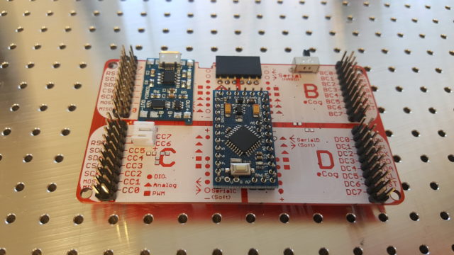
The advantage of soldering directly to the surface of the motherboard is that it leaves more space inside the enclosure for your battery and eCogs and it reduces the danger of the pin headers puncturing your battery.
Solder to the surface
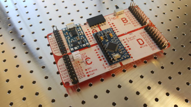
Step 1 – Attach one row of a male header to just hold the Arduino Mini Pro module in place (do not solder the male header pins).
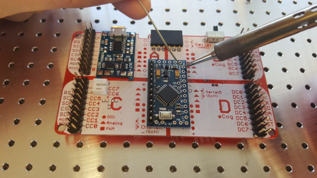
 Step 2 – Solder the empty pin holes – make sure that enough solder is used to flow through the holes and make a solid solder joint with the holes underneath.
Step 3 – Remove the male pin headers that were holding the board in place.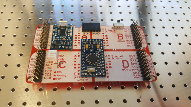
Step 4 – Solder the remaining holes.
Step 5 – Flip the board over and ensure that solder has flowed all the way down to the bottom of the holes. If not then solder from the bottom side.
Solder to Male Headers
This is the most common way to solder a device like the Arduino Mini Pro module to a board but results in less room for your components and lots of sharp pin headers to puncture your battery…
Step 1 – Place the pin headers in the motherboard so that they are held in place.
Step 2 – Then place the Arduino Mini Pro module over the pin headers and solder the module to the pin headers.
Step 3 (Not Pictured) – Flip the GadgetBox motherboard over and solder the male pin headers to the bottom of the motherboard.
To measure the battery (Optional)
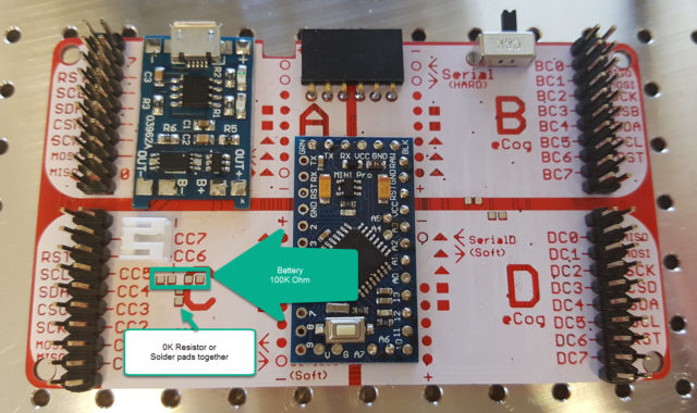
The GadgetBox Mini Pro (clone) Motherboard has an option to measure the battery voltage using the GB5 Analog pin. It is not populated by default because you will give up the use of GB5 if you want to measure your battery voltage. 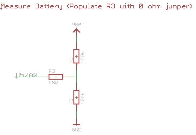
To measure the battery voltage place two 100K ohm 0805 SMT resistors in the R2 and R5 locations and place a 0K ohm 0805 resistor or just solder the two pads of R3 together:
In your sketch you measure the voltage by reading the analog pin at GB5 and then doubling the value to get the voltage.
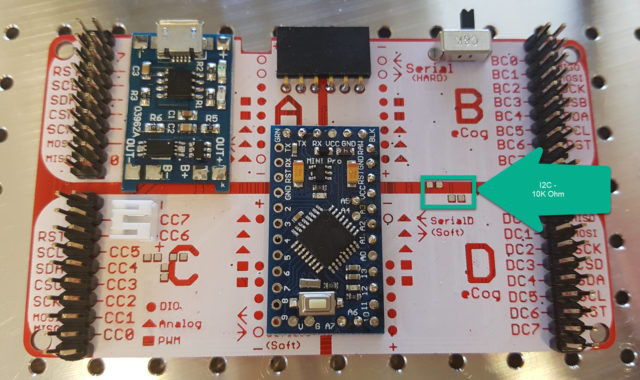
I2C Pullups (Optional)
There are pads to add 10K pullup resistors on the I2C pins if needed. In our testing so far they are not needed because most I2C modules already have pullup resistors on them. The pads are there just in case they are ever needed.
Power Management
Power and battery charging is provided by a TP4056 USB charging module (datasheet).
This USB Charging module can be used to provide power to the Arduino Mini Pro module through the USB connector or the battery connector. The USB connector is only used for power and charging, it is not possible to program the Arduino Mini Pro module through this connector. Instead you should use a FT232RL module and the FTDI serial header to program the Arduino Mini Pro module.
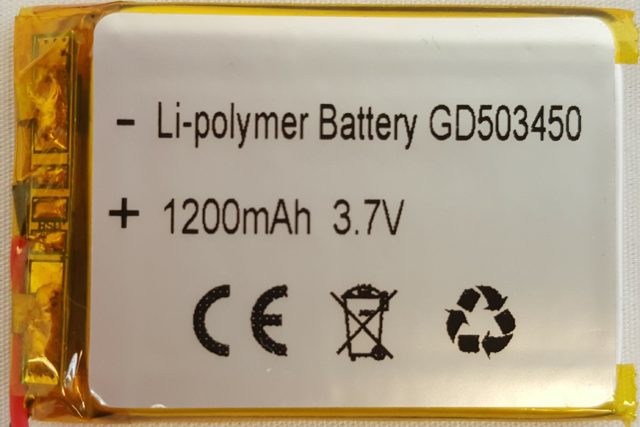
The USB Charging module is able to charge single cell lithium-ion batteries with a maximum charging current of 1000mA. The R3 resistor controls the maximum amount of charging current that the module provides to the battery. By default the charging module has a resistor of 1.2k which means it is set to provide a charging current of 1000mA. It is critical that you change this resistor if you are going to be charging batteries with less then 1000mAh capacity. As a rule of thumb, for safe charging, you should charge a battery at 1C. But wait, what does that mean exactly? This is a serious topic that can lead to problems such as your battery catching fire so we should be careful to fully explore and understand this rule. Let’s start with a quick review of how battery capacity works. Your battery will have a number on it that designates the C. For example, the following battery is marked with 1200mAh:
So our battery has a C (capacity) of 1200mAh which means that when this battery is fully charged we can expect to get a current of 1200mA out of this battery for 1 hour. Now, the current draw is determined by our circuit, if we have a circuit that draws 1200mA (this is an unusually high current draw) then we will be able to power this circuit for 1 hour. If our circuit only draws 200mA (more normal number) then we would get 1200mAh/200mA = 6 hours of operation out of this battery.
When we charge the battery we have to be careful to follow the rule of not putting more the 1C of current into the battery. If we do not follow this rule then we risk damaging the battery and shortening its life or even causing a fire… Bad things happen so please be very careful to follow this rule. This rule basically says, do not put more current into the battery then what is marked on the battery, which is 1C. So in the case of our battery it is marked with 1200mAh which means that the max current we can use to charge this battery is 1200mA. Since our charging module can only supply 1000mA we are safe with this battery. We are never going to charge at greater then 1C…
But lets say we have one of those nice drone batteries that have a capacity of 380mAh printed on it. We know right off the bat that this is going to be a problem with the default configuration for the charging module, anything with a battery capacity of less then 1000mAh will be charging too high. With a battery that has 380mAh printed on it we want to be providing a maximum of 380mA of current when we charge it. The following table tells us what we need to change the R3 resistor to:
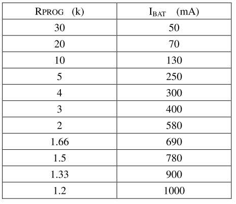
For our 380mAh battery we should select the row on the table that provides 300mA of current to the battery (Ibat) which calls for a 4k ohm resistor. So we would replace the 1.2k ohm resistor that is currently populated in R3 with a 4k ohm resistor which will limit the current that we provide to the battery to 300mA.
Once you have replaced the resistor the simplest way to verify that you are charging safely is to verify that a fully discharged battery takes more then one hour to charge. So run the battery in your circuit until it runs out of juice and your project dies, most Lithium-Ion batteries these days have a cutoff circuit that turns the battery off when it is depleted so this is safe to do. Then plug power into the charging module and you should see the red led come on, start a timer now. Monitor your battery while it charges to make sure it does not get hot, if it does then remove it immediately and double check your work. If all goes well you should see the red led go off and the blue led come on when the battery is charged. If it takes less then an hour for the blue led to come on then you know you are charging at more then 1C and have a dangerous situation. If it takes more then 1 hour then you should be charging at less then 1C and are safe.
To be 100% sure what is going on we recommend using a Charger Doctor module which can be found for less then $10 on eBay. You just plug the Charger Doctor into your USB port and then the USB cable for the TP4056 module into the other side and it gives you an exact measurement of the current you are putting into the battery, the mAh you have provided, and the elapsed time. It is a great tool for making sure you are charging safely and as a nice bonus it can be used to determine how much current your circuit draws so you can figure out how long your battery should last. It is much, much easier then putting a multi-meter in series with your battery.
One final thing to consider when charging your batteries is that most USB ports on computers will only provide 500mA. So if you are connecting the charger to a computer then you will most likely not be achieving 1000mA of current into the battery which will affect how long it takes to charge the battery. To get 1000mA of current you will need a cell phone charger or some AC USB adapter that is rated to provide over 1000mA of current. On the flip side, if you have a 500mAh battery and do not want to replace the resistor on the TP4056 USB charging module you might be able to effectively limit the current to 1C by always using a computer USB port, or finding a wall adapter that is only capable of providing 500mA of current.
If you have any questions please ask for clarification in the GadgetBox forum so we can help you figure out what is safe for your battery.
Using Arduino IDE
Install GadgetBox Library
The first thing you will need is to install the GadgetBox library.
You can download the GadgetBox Library from the Github page.
Click the, “Download” button and save to your computer.
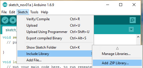
Add the library to the Arduino IDE (you may need to restart the Arduino IDE after adding the library)
Use GadgetBox Pin Names
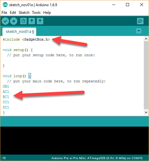
In order to use the GadgetBox numbering scheme you need to have the library installed and you need to include the library in your sketches. To include the library you should add the following line at the top of your sketch:
#include <GadgetBox.h>
You should see that any GadgetBox pin names that you use will be a blue color:
Please refer to the pin diagram to see the GadgetBox names you can use (GB0-GB15) and the eCog names you can use (xC0-xC7).
Select the Board Type
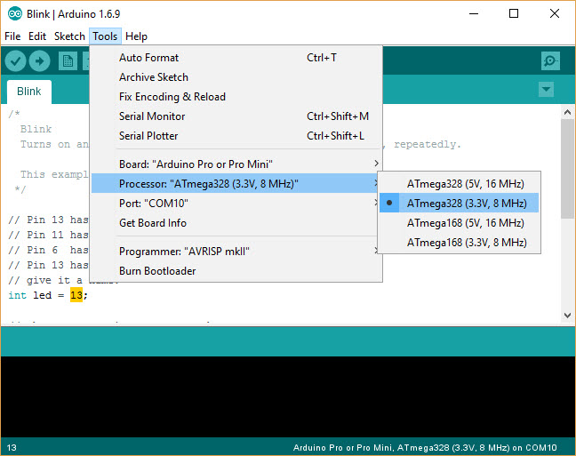
From the Tools Menu select, “Board/Arduino Pro or Pro Mini”
Then select, “Tools/Processor/ATmega328 (3.3V, 8MHz)”
Programming the Arduino Mini Pro (Clone) Module
You will need an FTDI USB to Serial module to write a sketch to the Arduino Mini Pro module.
Connect the FTDI USB to Serial module to the programming header on the GadgetBox and to a USB port on your computer.
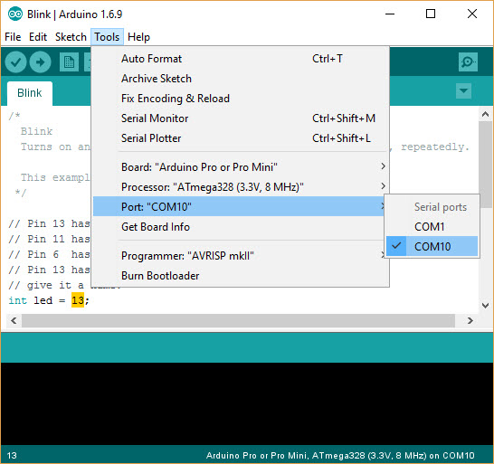
You should see a serial port show up under the Arduino IDE for your FTDI USB to Serial module:
Press the “Upload” icon to load your sketch to the Arduino Mini Pro module.
Universal eCog Scheme
The GadgetBox MPC uses the Universal eCog Scheme to organize the pins available on the Arduino Mini Pro Clone modules into a format that allows the most flexibility in adding hardware modules. These hardware modules are called eCogs (short for electronic Cogs) and the Universal eCog Scheme allows you to connect four eCogs to the Arduino Mini Pro Clone motherboard while managing pin conflict and pin function requirements by simply matching shapes and avoiding overlap.
Background and Basic Assumptions
The Universal eCog Scheme came from years of development of the Papilio FPGA platform. On an FPGA there are a ton of pins and even better, each pin can take on any function such as UART, SPI, or I2C. The Papilio FPGA platform has something called Wings where power and 8 I/O pins are provided, allowing you to easily add new hardware to the FPGA. Since any pin can take on any function there was no need to specify anything more then that. I happily made hundreds of Wing designs over the years and in that process I realized there was a distinct pattern. It seemed that the majority of the time the Wings fit within the following parameters:
- The single most important realization was that there are really just four types of Wings
- SPI based
- I2C based
- UART based
- GPIO based
- GPIO based peripherals often use less then 4 pins
- Almost all peripherals these days are 3.3V
With this realization came the further realization that it is possible to make a scheme for connecting peripherals that would work with microcontrollers and would enable the creation of universal hardware modules that could be used with any microcontroller platform! If you have an SD card for the Arduino it should also work with the ESP8266, Raspberry Pi, Photon, or anything else that comes along. If these microcontrollers have their pins re-organized into the Universal eCog Scheme then we can have Universal hardware modules that just snap in and work on any platform.
Ideal Universal eCog Scheme
The next step was to define what the Ideal Universal eCog Scheme (IUeS) would look like. First of all, we define four eCog slots. eCog is short for electronic Cog and is a self contained hardware module that takes its power from the eCog slot and provides functionality back to the microcontroller over the GPIO, SPI, I2C, or UART pins. Users should be able to just plug the eCog module in and start programming, freeing them up from worrying about the electronics. Each of the four eCog slots provide the following functionality:
- 8 GPIO pins
- Dedicated pins for the SPI bus with its own CS (Chip Select) pin
- Dedicated pins for the I2C bus
- Access to its own UART
In a perfect world all of our microcontrollers would have enough pins to give the four eCog slots all of the above functionality, but unfortunately that is rarely the case. In most cases we have to share pins in order to deal with the limitations of the microcontrollers and realize the Universal eCog Scheme. The great news is that even with sharing some of these pins we can create a very useful and easy to use connection scheme and create Universal hardware modules. We just need a way to communicate how our device deviates from the ideal and how to deal with that.
Strategy used when the Ideal Universal eCog Scheme is not Possible
When the Ideal Universal eCog Scheme is not possible and pins have to be shared this is the strategy that is followed:
- The I2C and SPI buses get the first priority
- Two pins for the I2C bus are routed to all four eCogs, 10K pullups are included.
- Seven pins are allocated for the SPI bus. Three shared pins MOSI, MISO, SCK. Each eCog gets its own dedicated CS (Chip Select) pin.
- Hardware UART pins are placed at the first two GPIO pin locations for each eCog. If there is not enough hardware UARTs then Software UARTs are used if possible.
- All remaining GPIO is placed, if there is only 16 GPIO pins available then those 16 pins are shared between the 4 eCog slots by sharing AC7 with BC0 and all the way down the line until CC0 is shared with DC7. This scheme gives each eCog 4 pins to itself and 8 pins if the adjacent eCog slot is occupied by a SPI or I2C device or left empty.
- If there is less then 16 GPIO pins then the CS pins for SPI is shared with the first pin of each eCog.
- If there is even fewer GPIO pins then start filling GPIO pins at BC0 and go sequentially as far a possible sharing with AC7 and so on until GPIO pins run out.
- When placing the GPIO pins Analog and PWM pins should be placed as following:
- Place Analog pins starting in the middle of the 16 GPIO pins. So start with GB7 and GB8 and move out to GB6 and GB5 and GB8 and GB10. The implications of this is that Analog pins will only work with eCogs connected to the A and D slots.
- PWM pins will be placed in the middle of each eCog. If there are four PWM pins then they are placed at GB3 and GB4 and GB11 and GB12. The implication of this is that if only one PWM pin is used it will work in any eCog slot.
Phew! This is a lot of hard to process information… Don’t worry, it’s just here for documentation purposes just in case anyone needs it at some point. It’s not necessary to read or understand in order to use the GadgetBox and the Universal eCog Scheme.
Downloads
Datasheets
TP4056 Module – TP4056 Datasheet – DW01 Datasheet
Arduino Mini Pro – ATmega328p Datasheet
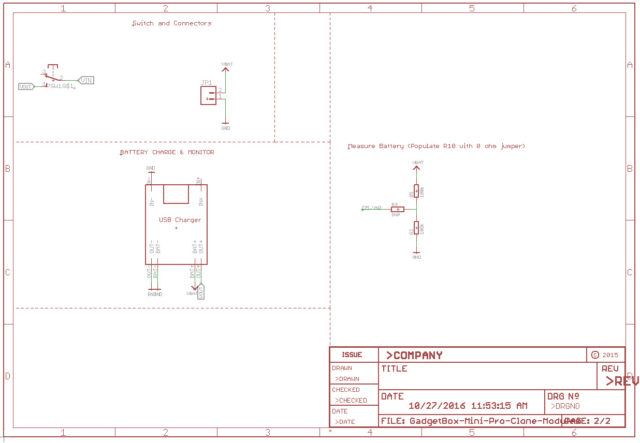
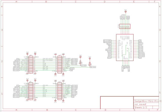
Schematic
Github Sources
License

GadgetBox by Jack Gassett is licensed under a Creative Commons Attribution-ShareAlike 4.0 International License.

