• Home
  • Products
    • Papilio FPGA
    • Arcade MegaWing
    • RetroCade MegaWing
    • LogicStart MegaWing
    • Logic Sniffer
    • Papilio Wings
  • Store
    • Gadget Factory Store
    • India Store
    • Distributers
  • Wikis
    • Papilio Wiki
    • Arcade Wiki
    • RetroCade Wiki
    • Logic Sniffer Wiki
  • Forum
  • Showcase
  • Downloads
  • Source Code
  • Home
  • Products
    • Papilio FPGA
    • Arcade MegaWing
    • RetroCade MegaWing
    • LogicStart MegaWing
    • Logic Sniffer
    • Papilio Wings
  • Store
    • Gadget Factory Store
    • India Store
    • Distributers
  • Wikis
    • Papilio Wiki
    • Arcade Wiki
    • RetroCade Wiki
    • Logic Sniffer Wiki
  • Forum
  • Showcase
  • Downloads
  • Source Code
Previous Next

DesignLab – Using the IDE for the first time!

Posted by: Jack Gassett , April 3, 2015

If you are just getting started with the DesignLab IDE and are not sure where to start, then this tutorial is for you! Learn how to use an existing example and load an FPGA circuit and corresponding sketch to your Papilio board.

Open QuickStart Sketch

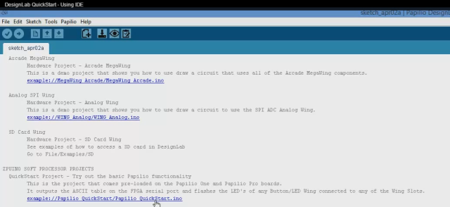
Once you’ve opened the DesignLab IDE you will find yourself in a table of contents page. Scroll down to find the Papilio DUO Quickstart sketch or the Papilio Pro/One Quickstart sketch.

Open Quickstart Sketch

Video Clip of Opening the Quickstart Sketch

Select the Board Type and Serial Port

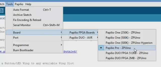
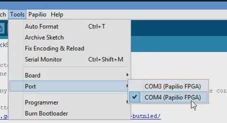
It is important to select the board type and serial port that matches the Papilio board you are using.

Select Board Type

Board Type

Important – Choose the board type that corresponds to your board. We have selected Papilio Pro here, but you may need to select Papilio DUO or Papilio One.

Select Serial Port

Serial Port

For the Papilio One and Papilio Pro you will want to select the second COM port that shows up. The Papilio DUO will only have a single COM port to select.

Video Clip of Selecting the Board Type and Serial Port

Load Circuit to FPGA

DesignLab adds a FPGA circuit to every sketch. In this step you want to load the circuit to the FPGA.

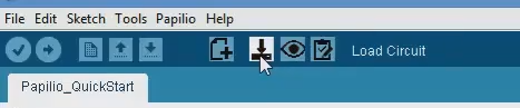
There are three new icons in the DesignLab editor window for working with circuits. You can use these icons to:

Load Circuit Icon (Do this now):

Load Circuit

Verify the circuit is loaded:

Done Loading Circuit

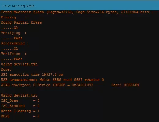
View the Circuit (Will open a view of the circuit in Adobe PDF Reader):
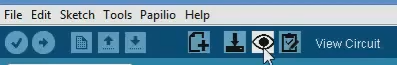
View Circuit

Please note that at this time the View Circuit needs to be manually created when the circuit is defined. This view may not be up to date if the printout was not made. We are working on a dynamic viewer for the circuit schematic files.

Edit the Circuit:

This will be covered in a later tutorial.

Video Clip of Loading and Viewing the Circuit

Upload Sketch

After the FPGA circuit is loaded you can load a sketch to it if it contains a ZPUino Soft Processor.

Load Sketch

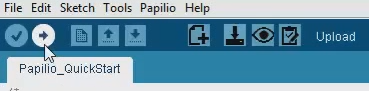
Video Clip of Uploading the Sketch

Verify the Sketch is Running

The Quickstart Sketch used in this tutorial outputs an ASCII Table over the serial port so we can open the Serial Monitor to verify that the sketch is running.

Click on the Serial Monitor icon:

Serial Monitor

Be sure that you set the Baud Rate to 9600 in the Serial Monitor.

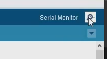
Video Clip of watching ASCII Output

Full Video Walkthrough

Tags: Quickstart

Comments

comments

About Gadget Factory

We make Open Source Hardware that is extremely Hackable, what we call Hack|Ware. Founded in 2009 by Aspiring Inventor Jack Gassett, we are hardware suppliers and inventors with a community focused approach. Home of the Papilio FPGA board and other open source hardware designs.

Located in Denver, Colorado just minutes away from beautiful Boulder, Colorado.

Gadget Factory Learning Site

Inspired by the excellent learning sites at Adafruit and Sparkfun we made our own learning site with tutorials about FPGA's, Electronics, and Making Open Source Hardware. If you have tutorials you would like to contribute please contact us at support@gadgetfactory.net.

If you have a project or code that you would like to share please post to the Showcase website.
© Gadget Factory 2013