• Home
  • Products
    • Papilio FPGA
    • Arcade MegaWing
    • RetroCade MegaWing
    • LogicStart MegaWing
    • Logic Sniffer
    • Papilio Wings
  • Store
    • Gadget Factory Store
    • India Store
    • Distributers
  • Wikis
    • Papilio Wiki
    • Arcade Wiki
    • RetroCade Wiki
    • Logic Sniffer Wiki
  • Forum
  • Showcase
  • Downloads
  • Source Code
  • Home
  • Products
    • Papilio FPGA
    • Arcade MegaWing
    • RetroCade MegaWing
    • LogicStart MegaWing
    • Logic Sniffer
    • Papilio Wings
  • Store
    • Gadget Factory Store
    • India Store
    • Distributers
  • Wikis
    • Papilio Wiki
    • Arcade Wiki
    • RetroCade Wiki
    • Logic Sniffer Wiki
  • Forum
  • Showcase
  • Downloads
  • Source Code
Previous Next

DesignLab “Hello World”

Posted by: Jack Gassett , April 3, 2015

Overview

Learn the work flow of DesignLab by making a simple “Hello World” project. This tutorial will show you how to use an existing DesignLab circuit and sketch, but it does not get into editing a circuit.

Create a new project

Once you’ve opened the DesignLab IDE click on the “New Papilio Project” icon to create a new project
Screen-Shot-2015-04-09-at-00.10.40

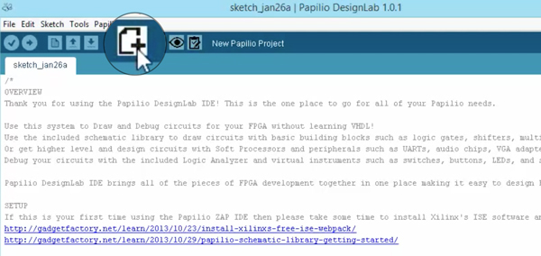
Video Clip of creating a new project:

Select the Board Type and Serial Port

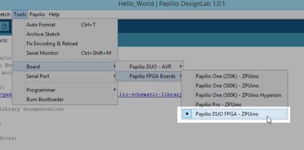
Make sure your board is plugged in and then select the board type and serial port that matches the Papilio board you are using.

Select Board Type

bordsType


Important: Choose the board type that corresponds to your board. We have selected Papilio DUO here, but you may need to select Papilio Pro or Papilio One.


Select Serial Port

Comport


 The Papilio DUO only have a single COM port to select but for the Papilio One and Papilio Pro two COM ports will show up and you will have to choose the second one.

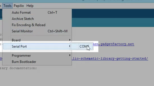
 Video Clip of selecting the board type and serial port:

Load Circuit to FPGA

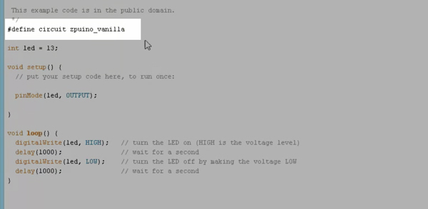
The first thing to do is to associate a blank ZPUino circuit with our sketcher by editing the code like this:

#define circuit zpuino_vanilla


ZPUino-circuit


Next step is to load the circuit to the FPGA by clicking the “Load Circuit” icon:

Load Circuit

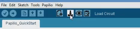
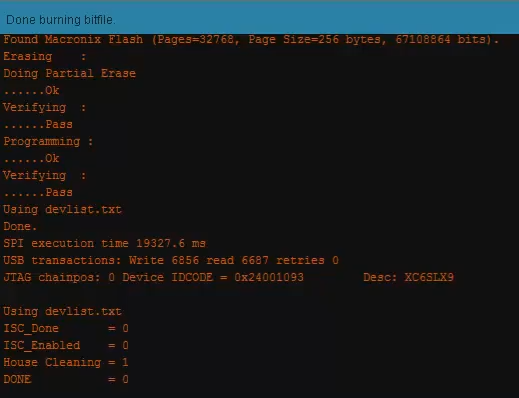
Verify the circuit is loaded:

Done Loading Circuit

 Video Clip of loading circuit to FPGA:

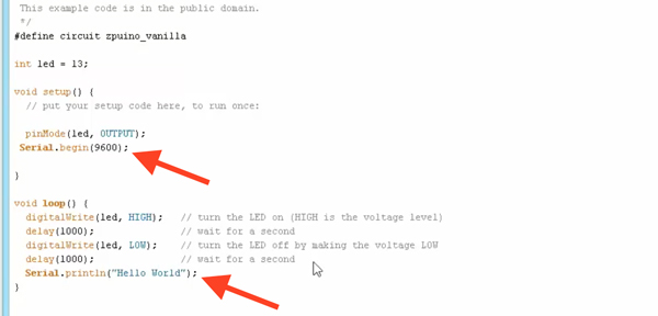
Write the “Hello World” sketch to the circuit

The default sketch just blinks LED on pin 13 so we should expand the code by adding these lines as mentioned below:

Serial.begin(9600);
Serial.println("Hello World");

HelloWorld

Video Clip of editing the sketch:
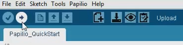
Upload Sketch

Now you can upload the updated sketch to the circuit by clicking on the “Upload” icon

Load Sketch

Video Clip of uploading the sketch:

Verify the Sketch is Running

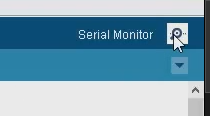
Now you should click on the Serial Monitor icon:

Serial Monitor

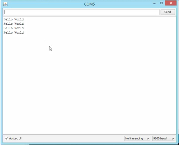
And on the serial monitor a “Hello World” will be printing:

monitor


Video Clip of uploading the sketch:

Full Video Walkthrough

Comments

comments

About Gadget Factory

We make Open Source Hardware that is extremely Hackable, what we call Hack|Ware. Founded in 2009 by Aspiring Inventor Jack Gassett, we are hardware suppliers and inventors with a community focused approach. Home of the Papilio FPGA board and other open source hardware designs.

Located in Denver, Colorado just minutes away from beautiful Boulder, Colorado.

Gadget Factory Learning Site

Inspired by the excellent learning sites at Adafruit and Sparkfun we made our own learning site with tutorials about FPGA's, Electronics, and Making Open Source Hardware. If you have tutorials you would like to contribute please contact us at support@gadgetfactory.net.

If you have a project or code that you would like to share please post to the Showcase website.
© Gadget Factory 2013