
Hardware
Papilio One?
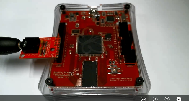
This tutorial is going to use the Papilio Pro with an Audio Wing connected to Wing Slot CH.
Hardware Video
Press fullscreen button in Youtube video and select HD 720p for best quality.
Create New Project
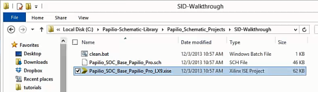
To make a new project you are going to want to navigate to the “Papilio_Schematic_Library\Papilio_Schematic_Projects” directory. Once there make a copy of the “Papilio_Schematic_Library_Base_Template” folder and rename it to whatever you want you project to be called. If you want a pre-existing example of this project please take a look at the sticky note on the side.
Go into your new directory and open the xise file for the Papilio Pro, this will cause Xilinx ISE to open the project.
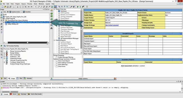
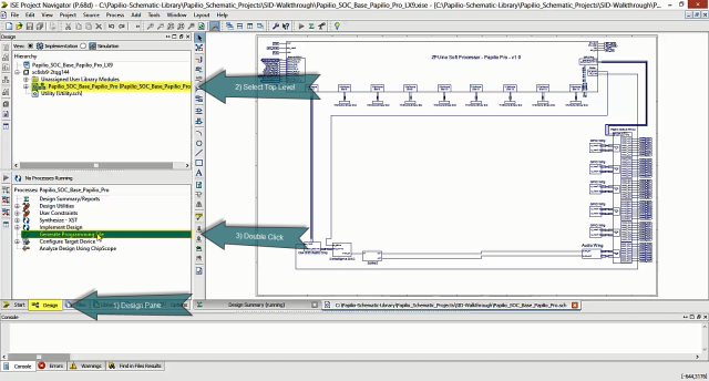
Once the project is open double click on the Top Level Schematic file in the Design/Hierarchy pane.
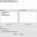 Warning – If you get a Symbol Library Error message that means that you do not have the Symbol Library setup in Xilinx ISE yet. Please follow the PSL Getting Started Guide to properly install the Symbol Library. You can also watch the walkthrough video for this tutorial, start at 4:40 to see how to fix the missing symbols.
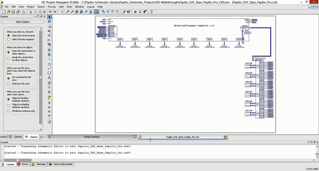
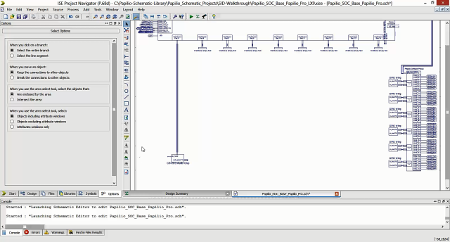
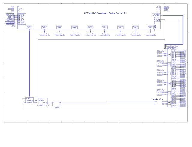
If everything is setup correctly you should see a base project that looks like this:
New Project Video
(Press fullscreen button in Youtube video and select HD 720p for best quality.)
Add SID Chip to Schematic
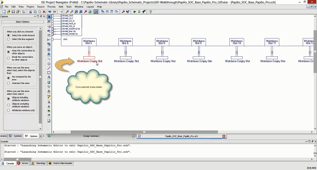
Clear Wishbone Slot 5
You want to remove the Wishbone_Empty_Device symbol and the attached nets from Wishbone Slot 5. Select all items and press the delete key.
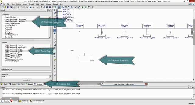
Add Commodore 64 SID Chip Symbol
1) Click Symbols tab
2) Choose “.Papilio Peripherals – Wishbone” in the Categories tab
3) Choose “AUDIO_zpuino_wb_sid6581” symbol
4) Drag the symbol onto your schematic page
5) Connect the SID symbol to Wishbone slot 5
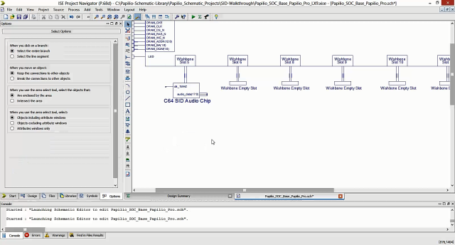
6) Drag down until it is lined up with Wing Slot CH
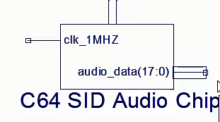
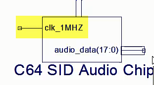
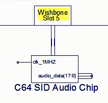
If we look closely at the schematic symbol for the C64 SID chip we see there are two connections. Any connections on the left are inputs and connections on the right are outputs. So we can see that the C64 SID chip is expecting a 1Mhz clock on the input and it will output audio data on an 18 bit wide output bus.
Add SID Video
(Press fullscreen button in Youtube video and select HD 720p for best quality.)
Supporting Circuitry
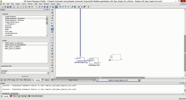
Add DeltaSigma DAC
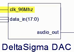
We will add the clocks a little bit later but for now we need to convert the digital audio data into something that we can output onto a single pin as an analog signal. The easiest way to do that is to push the digital audio data into a DeltaSigma DAC (Digital to Analog Converter).
1) Click Symbols tab
2) Choose “.Papilio Peripherals – Standalone” in the Categories tab
3) Choose “AUDIO_zpuino_sa_sigmadeltaDAC” symbol
4) Drag the symbol onto your schematic page and connect it to the output of the C64 SID Chip
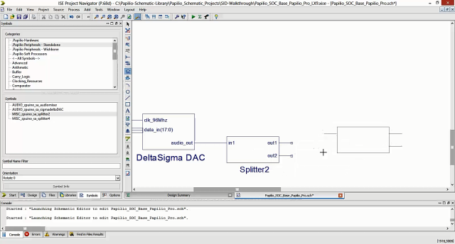
Add Two Channels
As you can see our DAC only outputs one audio channel, but we are going to connect to an Audio Wing that has two channels. We will need to split the single audio channel into two channels using the splitter.
1) Click Symbols tab
2) Choose “.Papilio Peripherals – Standalone” in the Categories tab
3) Choose “AUDIO_zpuino_sa_splitter2” symbol
4) Drag the symbol onto your schematic page and connect it to the output of the DeltaSigma DAC.
Delta Sigma DAC Video
(Press fullscreen button in Youtube video and select HD 720p for best quality.)
Splitter Video
(Press fullscreen button in Youtube video and select HD 720p for best quality.)
Connect Audio Wing to Wingslot CH
Now that we have two audio channels we need something to connect them to. With the Papilio Schematic Library it is easy to interface with physical hardware connected to your Papilio board. In this tutorial we are connecting an Audio Wing to Wingslot CH as shown in this picture.
In our schematic we can add our Audio Wing by removing the GPIO symbol from Wingslot CH and replacing it with the Audio Wing symbol. When we do that the features of the Audio Wing will be accessible to the rest of our schematic. In this case two audio channels will be available to connect to the splitter we just added.
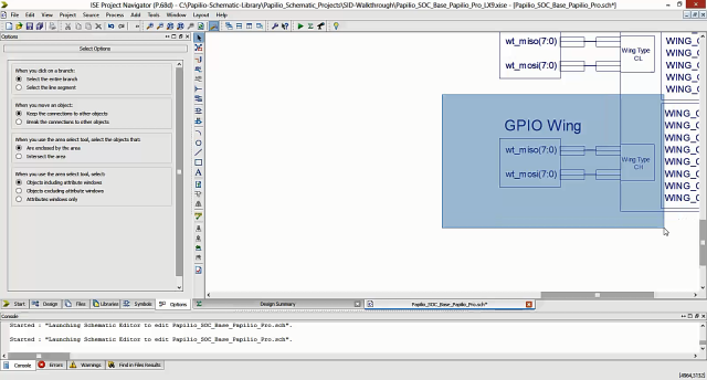
Remove GPIO Wing from Wingslot CH
Highlight the GPIO Wing and nets connected to Wingslot CH and press the delete key to remove them which will free up that wingslot for our Audio Wing.
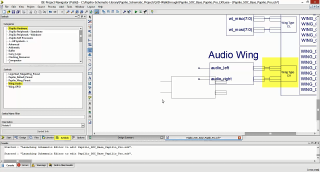
Add the Audio Wing
1) Click Symbols tab
2) Choose “.Papilio Hardware” in the Categories tab
3) Choose “Wing_Audio” symbol
4) Drag the symbol onto your schematic page and connect it to empty CH Wingslot.
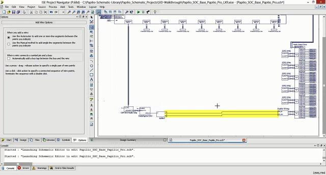
Draw Wires
The final step is to draw two wires connecting the splitter to the Audio Wing.
Audio Wing Video
(Press fullscreen button in Youtube video and select HD 720p for best quality.)
Connect Audio Wing Video
(Press fullscreen button in Youtube video and select HD 720p for best quality.)
Connect the Clocks
As we saw earlier the Commodore 64 SID chip requires a 1Mhz clock on its input.
The DeltaSigma DAC also requires an input clock, we can see that it wants a 96Mhz clock.
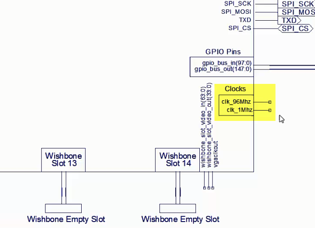
Connecting clocks is real easy in the Papilio Schematic Library, the Soft Processor will have clock outputs that you can use to drive the clock inputs you need. Remember inputs are on the left of a symbol and outputs are on the right of a symbol. Here are the clock outputs on the Soft Processor.
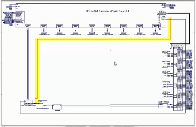
So all we have to do to connect the clocks is draw a wire between the clock output on the Soft Processor to the clock inputs of our SID chip and DeltaSigma DAC. You should be able to just click on each pin and let the auto router draw the connection for you.
1Mhz Clock
96Mhz Clock
Connect Clocks Video
(Press fullscreen button in Youtube video and select HD 720p for best quality.)
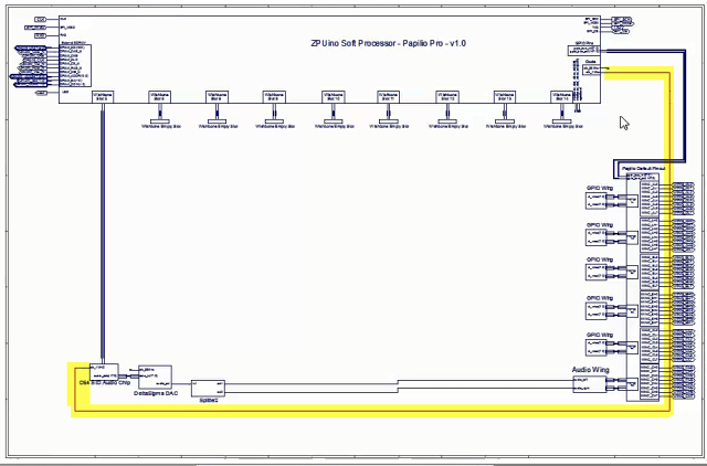
Finished Schematic
Your final schematic should look something like this.
Synthesize Bit File
Now that our schematic is complete we are ready to synthesize our custom design into a bit file that can be loaded to the Papilio FPGA board.
1) Click Design Pane
2) Hightlight Top Level design in the Hierarchy Pane (Top Level is the one with three boxes in a tree formation with the top box green.)
3) Double Click on Generate Programming File to start synthesizing the design.
You will see messages start to fly by on the Console window. This will take a little while so its a great time to take a break!
When the process is complete you should see a message that says, “Process ‘Generate Programming File’ completed successfully”.
Synthesize Project Video
(Press fullscreen button in Youtube video and select HD 720p for best quality.)
Load the Design to your Papilio
If the synthesis worked correctly then you will see a message that says, “Process ‘Generate Programming File’ completed succesfully.”
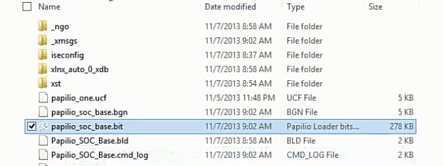
You will be able to find a newly created bit file in your project directory. Switch to the directory that you created the project in and look for a *.bit file. If you have not renamed the project it should be named, “papilio_soc_base.bit”.
At this point you will want to connect your Papilio FPGA board to a USB port on your computer.
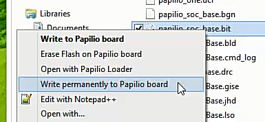
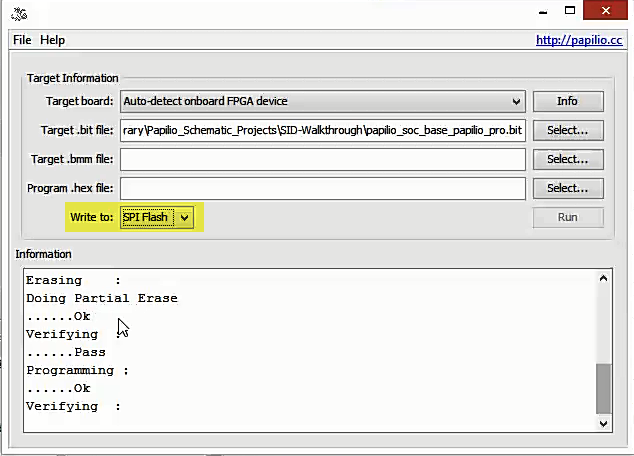
Right click on the bit file and select, “Write permanently to Papilio board”.
Load to Papilio Video
(Press fullscreen button in Youtube video and select HD 720p for best quality.)
Make Sketch in ZAP IDE
Next up is testing out our brand new electronics on a chip design! We are going to use a test sketch in the ZAP IDE to kick the tires and make sure everything works as expected.
Open up the latest version of the ZAP IDE, if you do not have it installed yet then please refer to the ZAP Getting Started Guide.
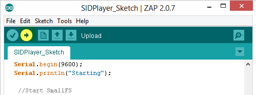
Open up a brand new sketch and paste the following code in:
/*
  Gadget Factory
  SID Audio Player Example

 SID libraries
 http://www.papilio.cc/index.php?n=Papilio.SID
 http://www.papilio.cc/index.php?n=Papilio.SIDVoice

 Hardware:
 Due to the size of the sid libraries this will only run on the Papilio Pro.
 This will work with any hardware with an audio jack: Audio Wing, LogicStart MegaWing, Arcade MegaWing, RetroCade MegaWing.

 ZPUino Variant:
 Use the Papilio Schematic Library to create a ZPUino that contains the SID audio component.

 created 2013
 by Jack Gassett
 http://www.gadgetfactory.net

 This example code is in the public domain.
 */
#define FREQ 17000          //Freq for all players

#include <SD.h>
#include "SID.h"
#include "SmallFS.h"
#include "ramFS.h"
#include "cbuffer.h"
#include "sidplayer.h"

SIDPLAYER sidplayer;

int sidplayercounter = 0;

void setup() {
  //delay(3000);
  // put your setup code here, to run once:
  Serial.begin(9600);
  Serial.println("Starting");

   //Start SmallFS
  if (SmallFS.begin()<0) {
	Serial.println("No SmalLFS found.");
  }
  else{
     Serial.println("SmallFS Started.");
  }

 //Setup timer for YM and mod players, this generates an interrupt at 1700hz
  TMR0CTL = 0;
  TMR0CNT = 0;
  TMR0CMP = ((CLK_FREQ/2) / FREQ )- 1;
  TMR0CTL = _BV(TCTLENA)|_BV(TCTLCCM)|_BV(TCTLDIR)|
  	_BV(TCTLCP0) | _BV(TCTLIEN);
  INTRMASK = BIT(INTRLINE_TIMER0); // Enable Timer0 interrupt
  INTRCTL=1;

  //Set what wishbone slot the sid device is connected to.
  sidplayer.setup(5);

  sidplayer.loadFile("music.sid");
  sidplayer.play(true);

}

void _zpu_interrupt()
{
  //Interrupt runs at 17KHz
  sidplayercounter++;
  //We need 50Hz for SID
  if (sidplayercounter == 340) {
    sidplayer.zpu_interrupt();
    sidplayercounter = 1;
  }
  TMR0CTL &= ~(BIT(TCTLIF));
}

void loop() {
  Serial.println("running");
  // put your main code here, to run repeatedly:
  if (sidplayer.getPlaying() == 1)
    sidplayer.audiofill();
}
Add a SID file to smallFs
The best way to make a SID file available to our sketch is to put it into SPI Flash using the smallFS library. It’s very easy to do, the library does all of the heavy lifting for us, we just need to create a directory named “smallfs” in our sketch directory, copy our sid file into it, and open that file in our sketch.
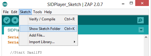
1) The first step is to open up our sketch’s project directory, be sure you have saved the code first, then go to “Sketch/Show Sketch Folder” in the ZAP IDE.
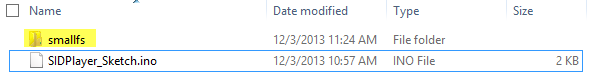
2) In your sketches folder create a new directory named “smallfs”.
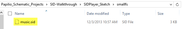
3) Copy a sid file of your choice into the smallfs directory and name it “music.sid”.
Open Sketch Video
(Press fullscreen button in Youtube video and select HD 720p for best quality.)
Important Parts of Sketch
Set sid filename
If you are wondering why we named the sid file in smallfs “music.sid” we can look at the sketch code and see that we have hard coded that name into the sketch.
We see the following code on line number 61:
sidplayer.loadFile("music.sid");
Set Wishbone Slot
A very important piece of the code is where we define what Wishbone slot the C64 SID chip is connected to. If we look back at our schematic we see that we connected the SID chip to Wishbone slot 5.
If we look at line 59 of the code we see the setup function for the sidplayer, we pass the Wishbone slot we have used in our Soft Processor as an option to the setup function.
//Set what wishbone slot the sid device is connected to.
sidplayer.setup(5);
If you have used a different Wishbone slot then just change this line to reflect your setup.
Wishbone Slot Video
(Press fullscreen button in Youtube video and select HD 720p for best quality.)
Upload Sketch and Hear Sweet Music!
Make sure your Papilio board is connected to the USB port and check that you have the correct settings.
Select the correct board type, you want ZPUino 1.0 and then choose the Vanilla variant for the type of Papilio board you have.
Ensure the second serial port is selected.
Click the “Upload” icon to load the sketch to your custom Soft Processor.
You should see the progress in the console window on the bottom portion of the ZAP IDE. The things to watch for are something about the SmallFS filesystem being found and that the Programming completed successfully.
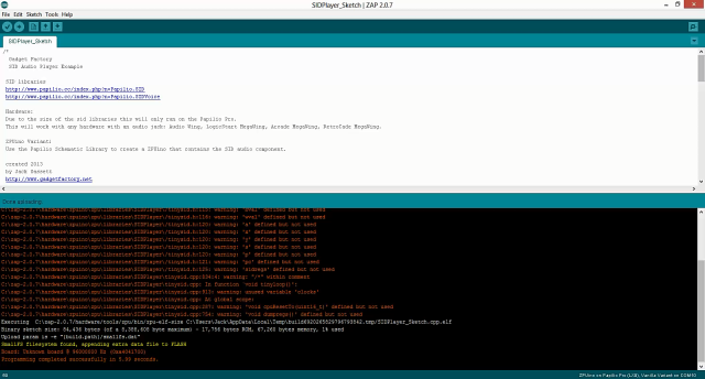
If all went well you should be hearing the sweet, sweet retro sounds of a SID file!
Upload Sketch Video
(Press fullscreen button in Youtube video and select HD 720p for best quality.)