
Setup
Make sure you are using the latest version of the Papilio Schematic Library. Take a look at the Papilio Schematic Library Getting Started Guide if you need to get setup.
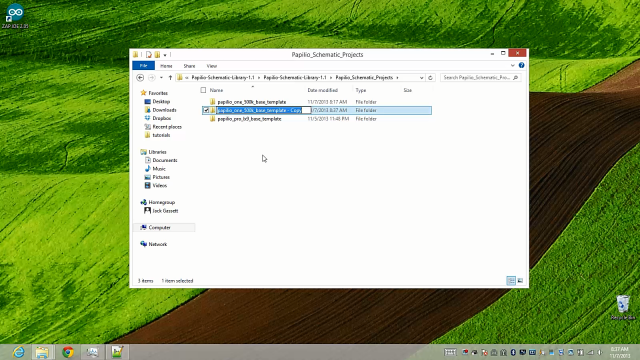
Make a copy of one of the base template directories found in the Papilio_Schematic_Projects folder. Choose the base template that corresponds with the type of hardware you will be using. Rename the folder to your desired project name.
Add UARTs to Schematic
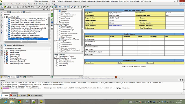
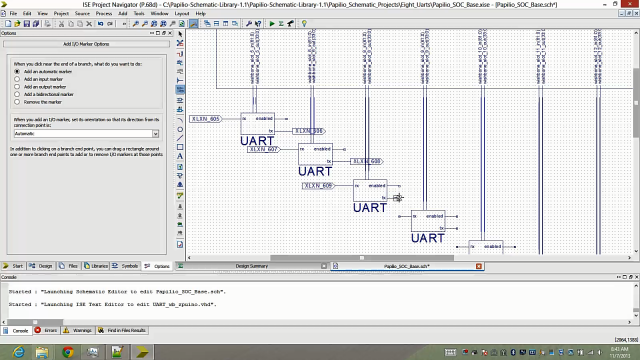
Open your newly created project directory and double click on the *.xise file to open up the Xilinx ISE Project Navigator software.
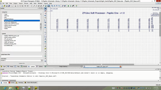
Find the top level schematic file in the Hierarchy pane and double click on it.
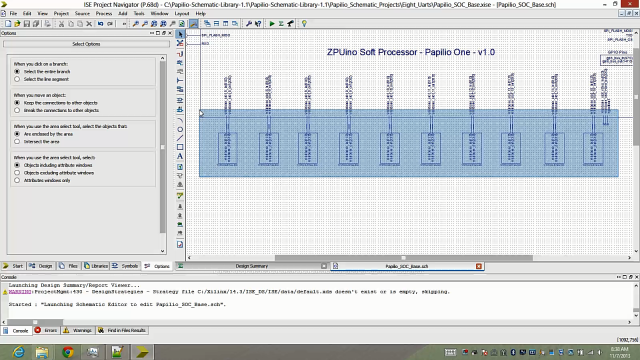
You will now see the base schematic with Empty Wishbone devices connected to all of the Wishbone slots. Now is a good time to experiment with zooming in and navigating around the schematic.
Delete Wishbone Empty Devices
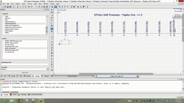
Delete as many of the Wishbone Empty Devices as you need to free up room for the UARTs you will be adding.
Highlight the Wishbone Empty Devices you wish to delete, in this example we will be deleting all of them, and press the delete key on your keyboard.
Add UARTs
There are two ways to add a new device to your schematic:
1) Click the “Add Symbol” icon in the toolbar.
![]()
2) Click on the “Symbols” tab in the pane to the left.
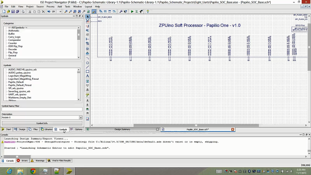
Either method will take you to the Symbols Pane where you will need to scroll down and find the “Papilio Peripherals” Category under the Categories sub-pane.
You will now see all of the available Papilio Peripheral devices in the Symbols sub-pane.
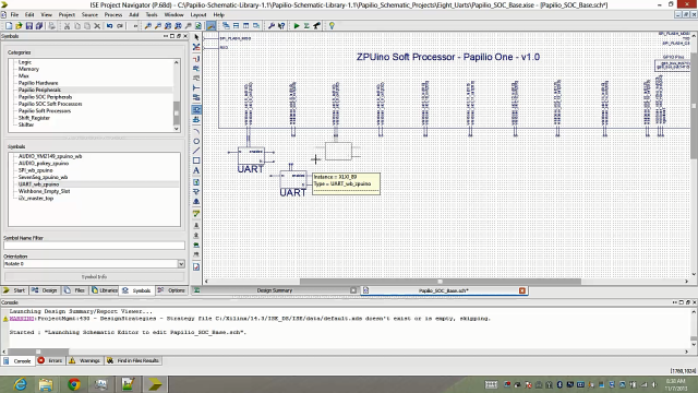
Select the UART-wb-zpuino symbol and move your mouse over the schematic pane. You will see that a UART symbol is attached to your mouse pointer.
You can now drag and drop the UART symbol onto the empty Wishbone slots. If you drop them correctly you will see that two net wires appear between the Wishbone slot connections and the UART.
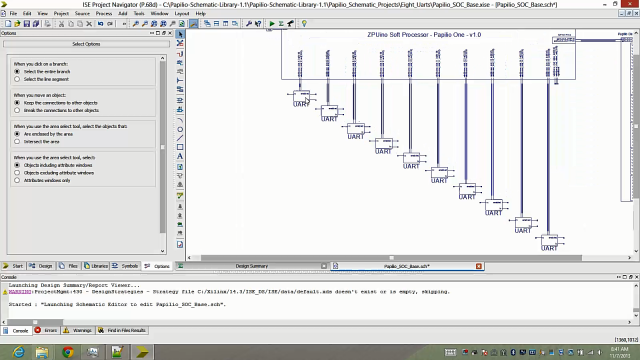
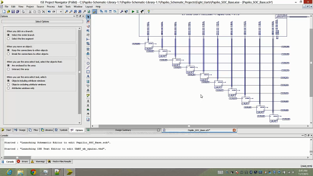
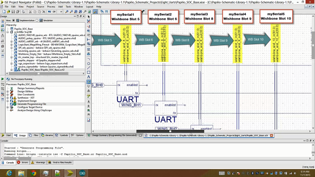
Connect all of your UARTs and arrange them however you desire, below is an example of one way to arrange them:
Connect External Pins to UARTs
Now that we have all the UARTs we need connected to the ZPUino Soft Processor we need to figure out how to connect all of these UARTs to the outside world. In the schematic editor the way to accomplish this is through the use of I/O markers.
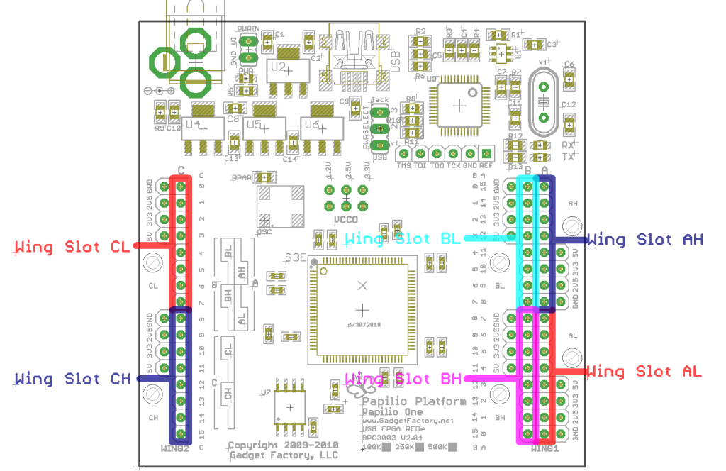
Lets talk a little bit about how the Papilio Schematic Library handles connecting to the physical pins of your Papilio FPGA board. We’ve gone through a lot of trial and error to get to the most dead simple, easiest way to deal with external pins in the schematic editor. Since it can become very tedious to deal with buses and bus taps in the schematic editor we have broken down each physical pin to its very own I/O marker. The Papilio FPGA has three 16 bit Wings which are marked as Wing A, B, and C. Each 16 bit Wing is further sub-divided into 8 bit Wings which are marked as AL, AH, BL, BH, CL, CH. AL designates the lowest 8 bits of the A row and AH designates the highest 8 bits of the A row. Here is a graphic that illustrates the Wing scheme:
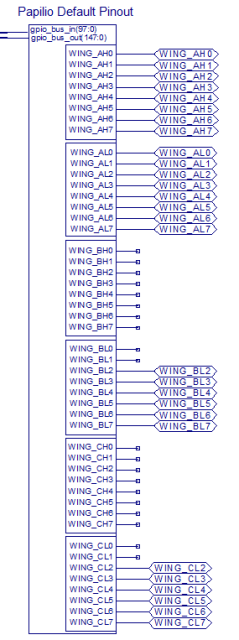
In the Papilio Schematic Library there is a Papilio Hardware category. In this category there are symbols to define the physical pins for the Papilio hardware you are using. If you have a LogicStart MegaWing connected to your Papilio then you will find a hardware symbol that has convenient connections for the hardware features of that board, such as the VGA pins, the seven segment pins, or the audio pins. If you do not have anything connected to the Papilio then there is a Papilio Default Pinout symbol (Figure 1) that breaks out all of the I/O pins and groups them into 8 bit Wing slots. If you leave the I/O markers of the schematic editor connected to the pins of the Papilio Default Pinout device then those pins will act as standard GPIO which can be controlled using the digitalRead() and digitalWrite() functions in the ZAP IDE. If however, you want to use those physical pins for some other purpose, such as connecting UART tx and rx pins, you can delete the I/O marker from the Papilio Default pinout symbol and then instead add an I/O marker with the same name to your desired pins. In the case of the UART example we would connect the deleted I/O marker to the tx and rx pins of our UART which would give our UART access to the outside world.

Add I/O Markers to UARTs
Click on the I/O Marker icon on the toolbar to the left and click once on each of the rx and tx pins of the UARTs. Leave “Enabled” unconnected since we will not use the enabled pin in this design.
(Optional) Move all tx I/O markers over to the right in order to make the design look cleaner.
Free up Physical Pins
Now that we have the UARTs connected to I/O markers, remember I/O markers define physical pins, we need to free up some of the physical pins. We do that by deleting I/O markers from the Papilio Default Pinout Symbol on the right. If you delete the I/O markers from the Papilio Default Pinout Symbol they will no longer be connected to GPIO and will be available for a dedicated purpose such as the rx and tx of our UARTs. Decide which pins you want to sacrifice and select and delete their I/O Markers.
Assign External Pins to UART I/O Markers
Now that we have freed up external pins from our GPIO symbol we can assign them to our UARTs. To do so you will need to use the Name icon on the left side of the screen.
Once the Name icon is selected you will want to type in the name of the pin that you want to use, it will be the same name as the I/O markers that you deleted earlier.
Click on all of the I/O markers to apply the correct external pin name.
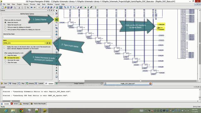
Repeat for all rx and tx pins of the newly added UARTs.
Synthesize your Design!
OK! It’s time for the magic, you are going to synthesize your bit file next.
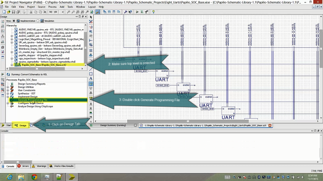
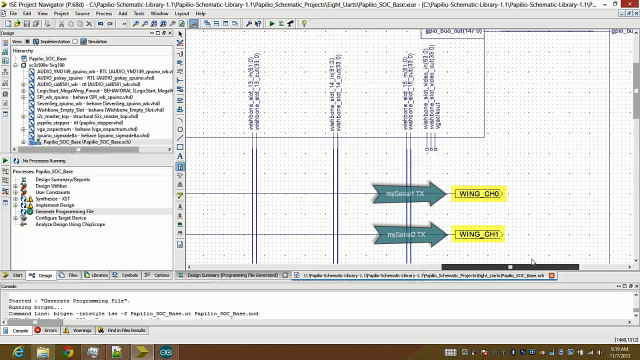
Click on the Design tab in the pane to the left of the screen.
Make sure the top level file is selected, you can tell it is the top level file because the icon to the left will have a tree diagram with the top node green.
Double click on the Generate Programming File option.
 This is going to take a while so go grab a cup of coffee!
Load the Design to your Papilio
If the synthesis worked correctly then you will see a message that says, “Process ‘Generate Programming File’ completed succesfully.”
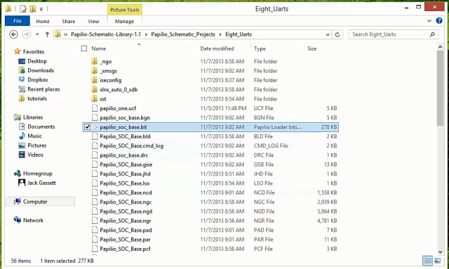
If you see that error message then you will be able to find a newly created bit file in your project directory. Switch to the directory that you created the project in and look for a *.bit file. If you have not renamed the project it should be named, “papilio_soc_base.bit”.
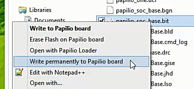
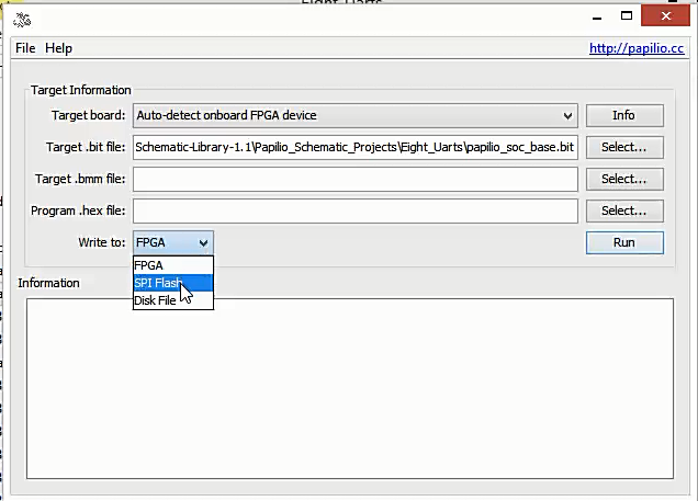
At this point you will want to connect your Papilio FPGA board to a USB port on your computer.
Right click on the bit file and select, “Write permanently to Papilio board”.
Run Test Sketch in ZAP IDE
Next up is testing out our brand new Soft Processor. We are going to use a test sketch in the ZAP IDE to kick the tires and make sure everything works as expected.
Open up the latest version of the ZAP IDE, if you do not have it installed yet then please refer to the ZAP Getting Started Guide.
Open up a brand new sketch and paste the following code in:
//This code assumes that you will use a jumper wire to connect the tx pins of the to UARTs to the rx pin of mySerial1. Refer to the schematic of your custom Soft Processor to determine what physical pin those signals are connected to.

//Instantiate the 10 serial ports and connect them to the Wishbone slots that we specified in our custom schematic design.
HardwareSerial mySerial1(5);
HardwareSerial mySerial2(6);
HardwareSerial mySerial3(8);
HardwareSerial mySerial4(9);
HardwareSerial mySerial5(10);
HardwareSerial mySerial6(11);
HardwareSerial mySerial7(12);
HardwareSerial mySerial8(13);
HardwareSerial mySerial9(14);
HardwareSerial mySerial10(15);

void setup() {
  //Start the 10 serial ports
  Serial.begin(9600);
  mySerial1.begin(9600);
  mySerial2.begin(9600);
  mySerial3.begin(9600);
  mySerial4.begin(9600);
  mySerial5.begin(9600);
  mySerial6.begin(9600);
  mySerial7.begin(9600);
  mySerial8.begin(9600);
  mySerial9.begin(9600);
  mySerial10.begin(9600);
}

void loop() {

  //Send a number out of mySerial1-10, read it on mySerial1, and send it out the USB serial port.
  mySerial1.write(1);
  mySerial2.write(2);
  mySerial3.write(3);
  mySerial4.write(4);
  mySerial5.write(5);
  mySerial6.write(6);
  mySerial7.write(7);
  mySerial8.write(8);
  mySerial9.write(9);
  mySerial10.write(10);
  if (mySerial1.available()) {
   Serial.println(mySerial1.read());
  }
  delay(500);
}
Make sure your Papilio board is connected to the USB port and check that you have the correct settings.
Select the correct board type, you want ZPUino 1.0 and then choose the Vanilla variant for the type of Papilio board you have.
Ensure the second serial port is selected.
Click the “Upload” icon to load the sketch to your custom Soft Processor.
Connect Code to Wishbone Slot
How does the code know what Wishbone Slot to communicate with? The very first section where we instantiate the UARTs is where we define what Wishbone Slot to use.
Take a look at the code again:
//Instantiate the 10 serial ports and connect them to the Wishbone slots that we specified in our custom schematic design.
HardwareSerial mySerial1(5);
HardwareSerial mySerial2(6);
HardwareSerial mySerial3(8);
HardwareSerial mySerial4(9);
HardwareSerial mySerial5(10);
HardwareSerial mySerial6(11);
HardwareSerial mySerial7(12);
HardwareSerial mySerial8(13);
HardwareSerial mySerial9(14);
HardwareSerial mySerial10(15);
When we call the constructor for the HardwareSerial object we are passing which Wishbone Slot our new serial object will be connected to. You can see that we set mySerial1 to Wishbone Slot 5, then mySerial2 to 6, we skip Wishbone slot 7, then we connect mySerial3 to 8 and so forth. The number that we are putting into the parentheses on these lines corresponds to the Wishbone slots that we connected our schematic to:
Test your Serial Ports
Now that you’ve synthesized and loaded your customized Soft Processor to the Papilio and then loaded a sketch to the Soft Processor you are ready to test things out.
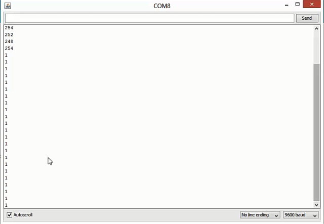
The sketch that we’ve loaded will cause all ten of the serial ports to output a number identifying which serial port they are on their tx pin. In turn the first serial port, mySerial1, will read its rx pin and forward anything it detects there over the Papilio’s USB serial port.
The end result is that you should be able to connect one end of a jumper wire to the rx pin of mySerial1 and then alternate between connecting the other end of the jumper to the tx pins of all your serial ports. As you connect the jumper pin to each of the serial ports you will see a number output over the USB Serial port that indicates which serial port is connected.
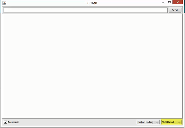
To get started you will want to click on the, “Serial Monitor” icon in the Arduino IDE.
When the serial monitor opens ensure that the baud rate is set to 9600.
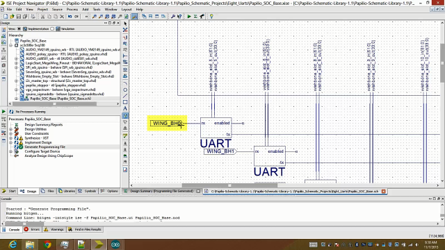
Next, you will want to look back at your schematic and determine which pin the rx signal of the first UART is connected to, if you followed the walk-through video then it should be connected to WING_BH0. You will want to connect one side of your jumper wire to this physical pin on the Papilio FPGA board.
Next you want to figure out what physical pins your tx signals are connected to. Scroll to the right and figure out what all of your tx pins are connected to.
Connect the other end of your jumper wire to the tx pins and you should now see output appearing in your serial monitor window that corresponds with the serial port that you are connected. It is normal to see garbage bytes when you are plugging the jumper into the physical pin, when you leave it connected it should show the correct number.
Congratulations! You have just created a custom ZPUino Soft Processor using the Papilio Schematic Library!